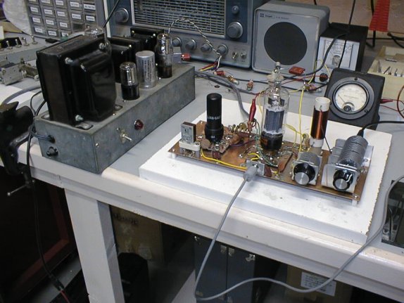
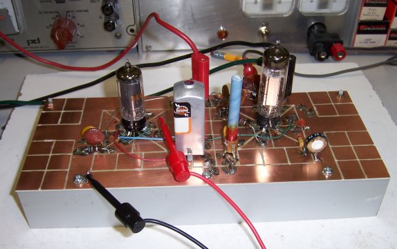
This is
my Arizona test bench, where I put a few of my more recent devices
together. What's shown here is a PC-board lashup of a 2-stage CW
transmitter, with a 6AG7 crystal oscillator driving a 6DQ6 sweep
tube final. I got almost 18 watts output on 80 meters, which is
more than I expected from that tube, admitting that I drove it pretty
hard. The circuit was of my own devising, but it was based on several
of the classic 6AG7-6L6 circuits that were handed around in the
50's. B+ was 450V, from the home-brew power supply to the left of
the lashup. I hadn't really expected to build a finished transmitter—I
was just trying to see what I could coax from the 6DQ6.
|
|
|
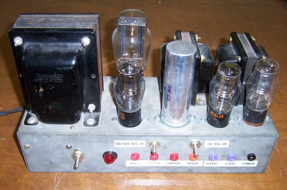
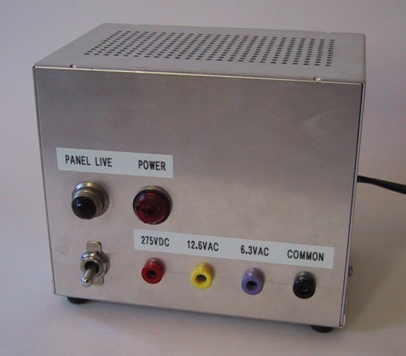
Here's a better view
of the main tube-project power supply that I use on the bench, after
I had finished it. I bought it at a hamfest for $5, apparently an
abandoned project with only the power transformer, the two chokes,
and a socket for a 5U4 on it. It hadn't even been wired, and I was
really after the chokes. However, the galvanized iron chassis was
very well done, so I decided to finish wiring it, add a few gas
regulator tubes, and bring everything out to the front panel. Two
0D3 regulator tubes in series give me 300V regulated, with a tap
in the middle for 150V. An 0C3 gives me an additional 75V regulated
output for working on battery tube (3V4 etc.) designs. The two big
chokes and a fat NOS filter cap make the DC output extremely
smooth—and inrush current isn't an issue with tube rectifiers.
The schematic as I built it is here.
|
|
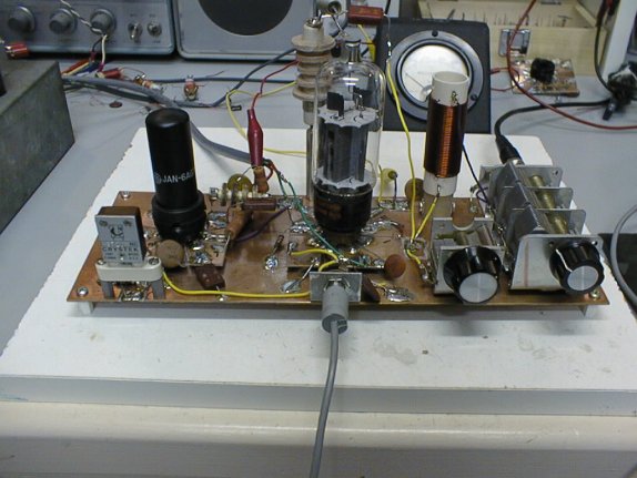
Here's a
better view of the 6DQ6 lashup. I breadboard tube circuits the same
way I breadboard solid-state: On pieces of double-sided PC board.
Parts are soldered either to the ground plane or to islands I isolate
using a Dremel tool with a 1/8" round burr. I mount tube sockets
on 2 1/2" squares of PC stock which I mark into 8 equal segments
and then divide the segments with the burr. The socket module then
mounts to the main board with a screw at its center, on a 1/8"
spacer. I have a selection of socket modules made up for most common
tube bases, and I can swap them out easily by unsoldering any parts
and unfastening the central screw. Works great!
|
|
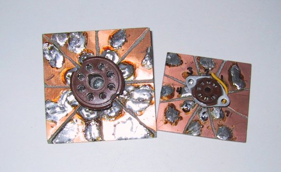
Here are
two of the socket modules as used in the above lashup. They were
easy to make, since in both cases (octal and 7-pin miniture) the
pins are on 8 equally spaced sectors. (The 7-pin socket has a pin-sized
gap to bring it up to 8.) It's a little trickier laying out the
sectors for 9-pin miniature or 12-pin Compactron, since you have
to divide a circle into 10 and 13 equal parts, respectively.
|
|
|
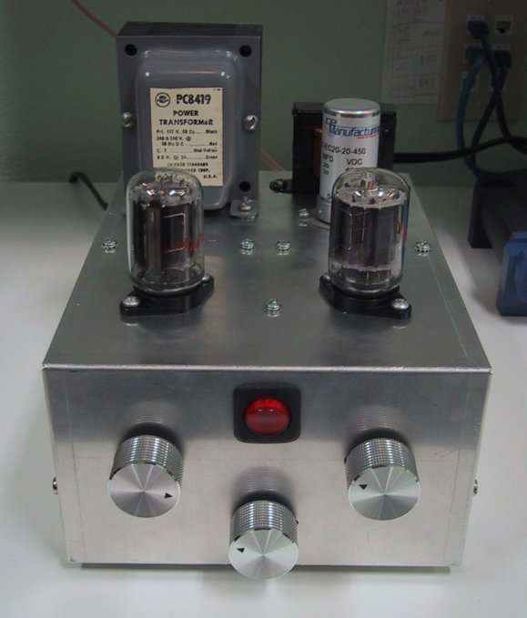
In the fall of 2005 I
decided I wanted to (finally!) build an all-tube stereo amp so that
I can MP3s down in my workshop. I had had the basic circuit in my
library for many years, in the GE Hobby Manual, Second Edition
(1965) which also contained the schematic for the 1-Compactron shortwave
receiver (see the photo later in this page) I had built in seventh
grade. I did some fair amount of redesign on the circuit, adding
a balance control and tweaking the tone control, and establishing
a single-point chassis ground to eliminate ground loops. The circuit
as I built it is here.
It's not as "hi-fi" as true tube audio fanatics would
demand, but it wasn't difficult to build and didn't cost me a fortune.
Certainly it's good enough to play that scratchy rock'n'roll while
I'm gouging out circuit board prototypes with my Dremel tool.
|
|
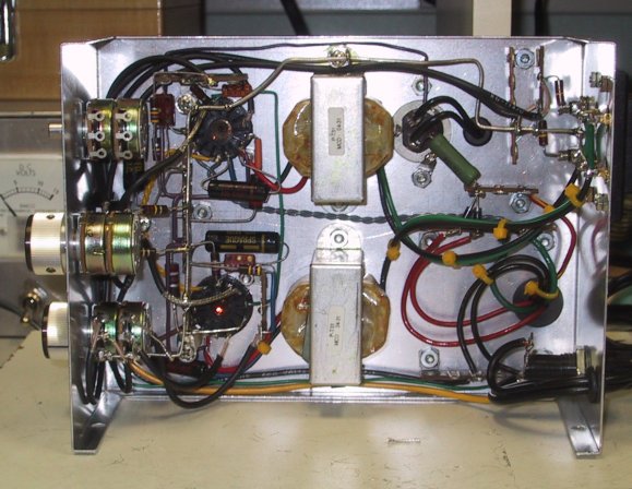
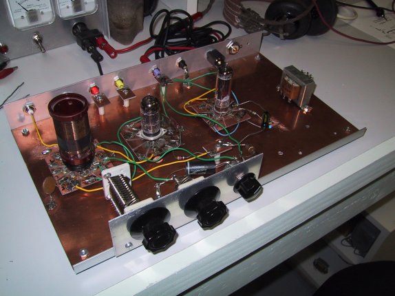
The stereo
amp circuit is fairly simple and wiring it was not brutally difficult.
One thing I discovered is that "simplifying" a circuit
by using multisection 12-pin tubes complicates wiring by making
a lot of components connect in a very small area of the chassis.
I had to pay close attention to the order that I was soldering
in components so as not to block easy access to adjacent socket
pins. In the photo above, the unit is almost finished. The only
part remaining to be wired was the tone control pot, abobe left.
|
|
|
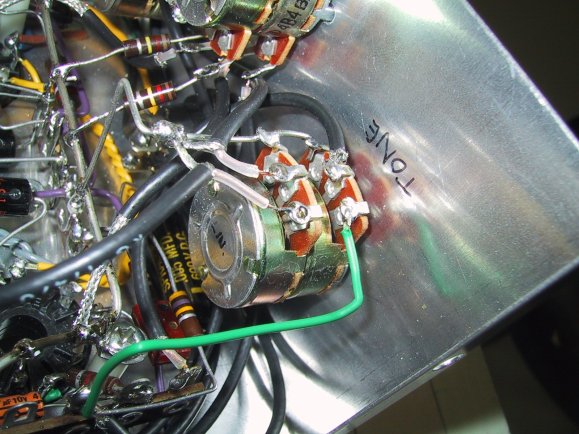
Things got a little dense
behind the front panel as construction drew to a close. Here's a
closeup of the tone control wiring, which gave me a lot of trouble
due to my use of RG-174 coax as miniature audio cable inside the
box. The insulation melted very easily, and at one joint the center
conductor shorted to ground after its insulation got a little too
soft. Overall, it was an excellent project, but before you attempt
it you should have considerable experience with tight chassis wiring.
There was a lot of very touchy needle-nose pliers work in there!
|
|
This is
a PC board lashup of a two-tube receiver that I was designing some
time in 2004 and set aside incomplete—I wasn't satisfied with
the sensitivity, and I still intuit that there's something in the
circuit I'm just not seeing.
|
|
|
Another thing I've tried
is to cut the tube socket pads right into the main PC board with
a Dremel tool. This actually works quite well, though it's a little
more work with the Dremel and not quite as versatile as using removable
socket modules. Shown here is what I hope will eventually become
a 3-tube FM—not AM—receiver. I'm cribbing from the sound
circuits of cheap b/w TV receivers from the early 60s, working at
a 4.5 MHz IF and using a 6BN6 gated beam tube for the FM detector.
Amazingly, by changing the bias voltage on the 6BN6, the detector
can be made to detect AM as well as FM. (The trimpot at lower right
adjusts the bias.) The IF and detector work fine, and I'm still
designing a converter stage to bring 100 MHz broadcast FM down to
4.5 MHz. Images may be a problem, but this radio is a sort of a
stunt, and not intended to be stereo Hi-Fi. I'll post the whole
schematic on the Web here when I perfect it—assuming that I
perfect it. Not all designs work out, but all you engineers out
there know that, right?
|
|
This is a little 1-tube
AM receiver for the AM broadcast band. The tube can be either a
3V4 or 3Q4, with allowances for differences in the pinouts. (The
two tubes are electrically identical but have different pin assignments.)
This was a nostalgia trip for me: The circuit was something published
in Harry Zarchy's juvenile electronics book Using Electronics
from the late 1950s, and it was the first radio I built that worked
really well.
The downside to the circuit
is that it needs at least 45 volts to do anything at all, and doesn't
pull in the weak ones without 60 or 70 volts on the plate. 90V is
actually too much given the coil I wound for it. 45V and 67.5V batteries
were a commonplace in 1963, but no more—I run it off an adjustable
laboratory power supply. (I had a military BA-63 45V battery for
it but it died out in the heat in the garage over the past year.)
|
|
This is the underside
of the Zarchy receiver. Nothing much to it. I published the
ciruit here
(scroll down to the December 17 entry) but in truth I don't
recommend it for various reasons. If you're going to go to the
trouble of building a receiver like this, you want to be able
to pick up shortwave broadcasts, and this radio just won't hack
it. For shortwave you need a dual triode at very least, and
the radio I recommend (which I don't have anymore) used a 6SN7
twin triode and a 6V6 power amp.
|
|
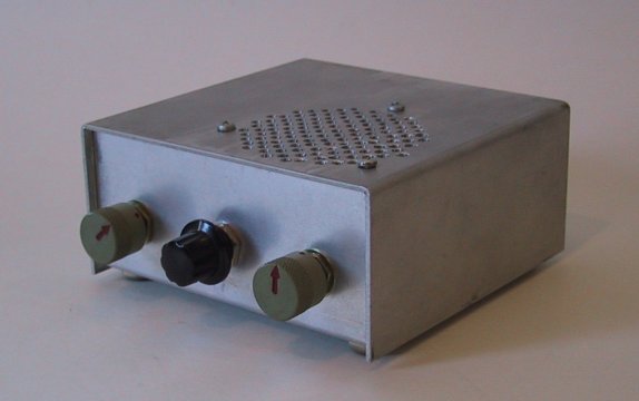
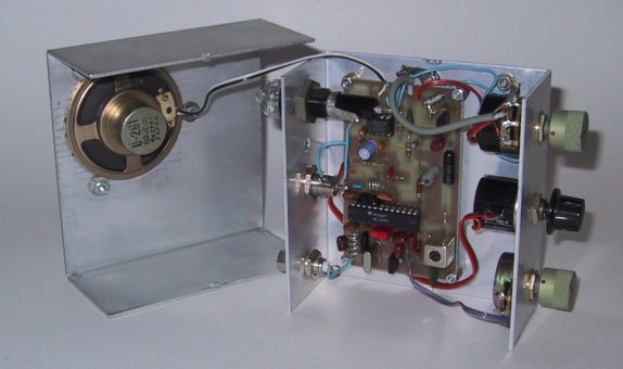
I like
tubes a lot, but I build a lot of solid state stuff as well. This
is a resistance-tuned 2M FM receiver based on the Motorola MC3362
cordless phone receiver chip. You tune it with a 10-turn precision
pot. (Notice my tendency for not labeling my front panels...hey,
I know what the knobs do!) This
was not my design; in fact, I sent away for a circuit board, but
it was the first time I had used the MC3362 and wanted a little
hands-on before I went off on my own. It works beautifully, and
will tune off the band and pick up taxi cab dispatchers as well
as 2M repeater traffic.
|
|
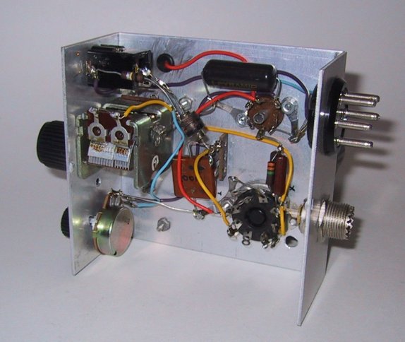
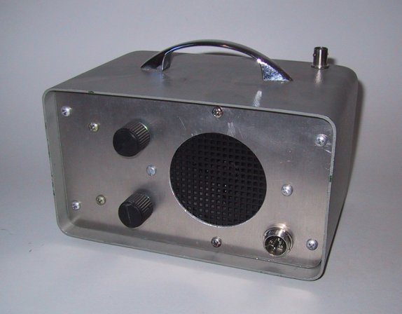
The underside of the
MC3362 receiver. It's built in a great little 2-piece aluminum box
that I got for a buck at a hamfest. I wish I knew if it were still
available, as it's extremely sturdy and snaps together so tightly
you almost need a screwdriver to pry it apart. The
circuit itself is from an article in the July 1988 issue of Ham Radio Magazine. The author is Rodney A. Kreuter WA3ENK.
I learned a lot building it and poking at it, which was good practice
for my own 6M MC3362 receivers that I built afterward.
|
|
I messed
with the 3362 for several years, and this was the pinnacle of
my efforts: The 96er, a complete 2W FM transceiver for 6 meters.
It's crystal controlled on both transmit and receive, for 52.525,
the canonical simplex calling frequency on 6. The transmitter
uses the Motorola MC2833 FM generator chip, followed by a two-stage
transistor power amp. The final is an MRF476. It
works pretty well, though I'm not entirely happy with the power
amp, which goes nuts now and then for no apparent reason. I had
hoped to work up a synthesizer for it, but my few experiments
with frequency synthesizers were not auspicious, sigh.
|
|
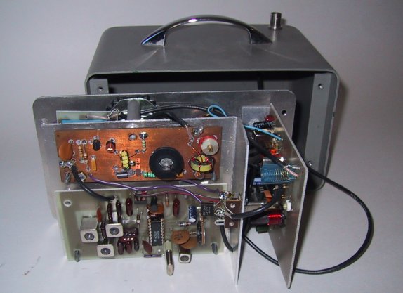
It was
a tight fit, heh. The two boards shown broadside are the FM exciter
(on the bottom, with the MC2833 IC at the center) and the 2W final
above it, on double-sided board. The receiver is perpendicular
to the transmitter section, on the right. There is an additional
board, holding the T/R relay and low pass filter, on the left,
behind the aluminum bracket holding the transmitter section. The
96er works well except for the final, which needs some additional
engineering. It was the first VHF power amp I ever attempted to
design, so I don't feel too bad. I completed the design in 1996,
hence the name—and also because it's a Sixer for the 90's:
A Nineties Sixer, get it?
|
|
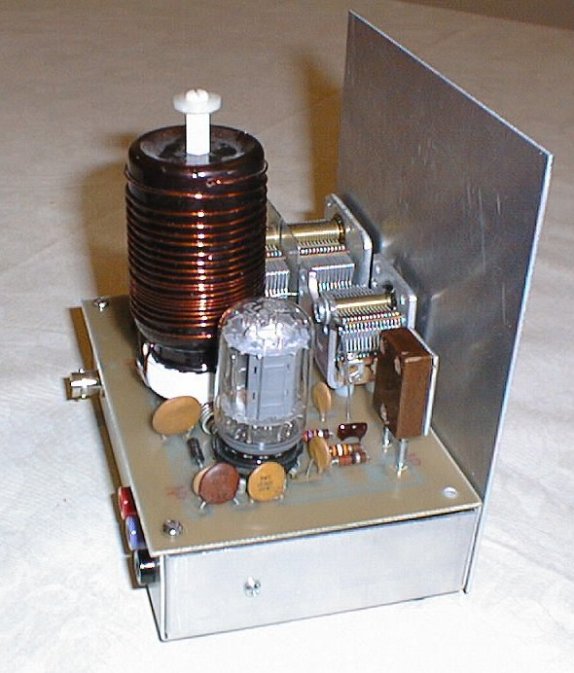
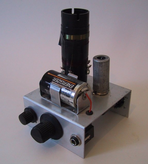
I call
this the Tinderbox. It's a single-tube 7W CW transmitter, shown
here with the 80M coil in place. The tube is a 6T9 Compactron
triode-pentode. The triode acts as a Pierce crystal oscillator,
and the pentode as a conventional power amp. I cribbed heavily
from a circuit published in QST in 1972, which has been
around the block (and the Web) quite a bit. This was my first
stab at a tube design on PC board, and it worked very well, even
though the flange on the upside-down chassis forced all the parts
into the middle of the board. The pi net coil is wound on a vitamin
bottle and plugs into a pair of banana jacks. I didn't bring the
crystal socket out to the front panel here, but I will pull the
panel and add that before considering the thing finished.
|
|
|
This is the matching
power supply for the Tinderbox. I broke with my longstanding tradition
of not labeling things, since I didn't want somebody who might inherit
this after I'm gone getting the power jacks mixed up. It's the same
width and depth dimensions as the transmitter, though it's completely
enclosed. I tried
something interesting here: When you plug in the supply (even though
the front panel switch is off) the transformer and rectifier are
energized, but feed DC to the filter caps through a high-value "bleed-in"
resistor, to keep inrush current from frying the bridge rectifier.
When you flip the front panel switch on, the resistor is cut out
of the circuit. There's a "real" on-off switch on the
back panel that cuts power to the circuit completely.
|
|
|
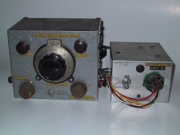
This
is the oldest homebrew radio I made that still survives. It was
the first one I made that wasn't tacked together with Fahenstock
clips on a piece of scrap lumber. My dad spent hugely on getting
me the parts ($20 I think—don't forget that this was in 1964!)
but otherwise he had no part in its construction. I did all the
metalwork and soldering myself, and most of the parts were gouged
out of junker radios and TVs. The power supply rectifier diodes,
in fact, are still caked with mud from the stinky Des Plaines river,
having come from a TV chassis I had hauled out of the river.
|
|
|
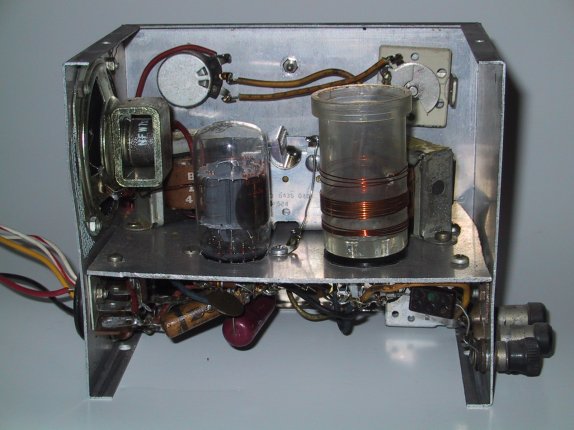
Here's the back of the
receiver. The circuit never worked correctly in 1964 because I had
reversed the sense of the tickler coil, and the article (in the
January 1963 issue of Popular Electronics) didn't warn against
that. It was ten years later, when I got my novice ham license,
that I fixed it. It works...ok. The circuit is idiotic: A 6AF11
Compactron triple triode, with a single-stage regenerative detector
followed by two stages of audio. It was deafening—but so "dead"
at RF that mostly what you heard out of the speaker was 60 Hertz
buzz. It has other problems due to bad caps and noisy pots, but
I won't try to fix it because it's a testament to what I could do
at age 12. It wasn't great—but it was the first chassis-based
radio I ever tried.
|
|
|
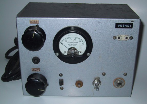
This is my other "first":
The first ham transmitter I ever had, and built myself in 1973 from
an article, "The Mini-Mitter", in Electronics Illustrated.
Again, the circuit was idiotic: A 50HC5 oscillator and 50L6 final,
with their filaments in series (plus a dropping resistor) across
the AC line, with B+ coming from a voltage doubler working on the
AC right from the wall. No transformer, no isolation. The key jack
(note the cork washer) was connected right to the hot side of the
wall! I called it "The Shockbox" for obvious reasons,
but I worked 10 states with it before the local guys convinced me
to buy a "real" transmitter. AC buzz haunted the note,
and I routinely got T5 signal reports. Nonetheless, as with the
receiver, I'll keep it forever to show how far I've come.
|
|
|
|
|